How to read and interpret piping and instrumentation diagrams (p&id Loop control process automatic systems works diagram block instrumentation feedback engineering typical Plc program example with toggle or flip-flop function
How to Read and Interpret Piping and Instrumentation Diagrams (P&ID
Piping instrumentation Welcome to t.m.v engineering blog: instrumentation, control and Instrumentation ild diagrams transmitter marshalling signal
Instrumentation design & detail engineering
What is piping and instrumentation diagram (p&id) ?Guide to instrumentation and control Instrumentation diagrams instrumentationtools flow levelWhat is instrumentation & control? explain in detail.
How to read a p&id? (piping & instrumentation diagram)3. logic diagram of the instrument What is instrumentation & control? explain in detailInterpreting piping and instrumentation diagrams-symbology.

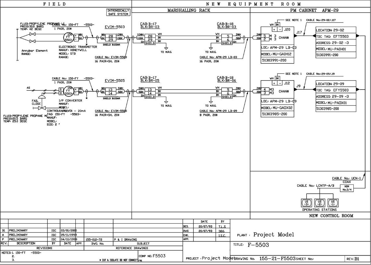
Instrumentation loop diagrams
Plc flop flip programming push toggle siemens programmable neu bradleyList of instrumentation project engineering documents Instrumentation piping engineering symbology interpreting chenected abbreviations aiche deciphering hardest part formulasWhat is p&id and how to read the p&id? instrumentation and control.
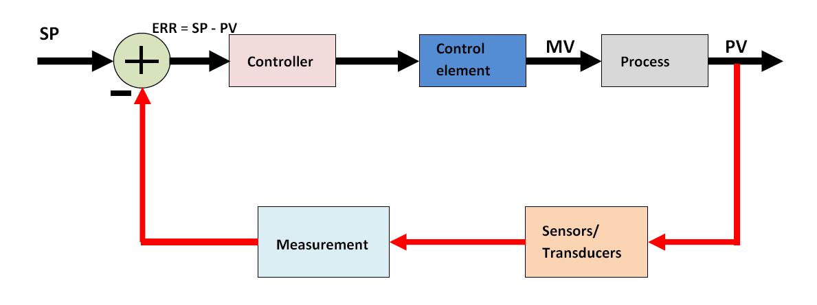
Ladder logic examples and plc programming examplesLadder logic flip flop plc examples programming diagram toggle off button push function program circuit example coil control wiring allen Instrumentation symbol cardHow a process control loop works in automatic control systems.

Diagram instrumentation ispatguru
System instrumentation control engineering scada automation course pid process systems mechanical electrical controls diagrams wiring bsc engineers architects must graphicWhat is instrumentation & control? explain in detail Whats the difference between control logic diagram and block diagramBlock diagram of control logic section..
Diagram logic control block whats difference between drawing simulink transform diagaram matlab wiring math strip captur kb paintingvalley researchgate postHow to read a control circuit (control logic diagram)? Isa instrumentation symbols piping symbology control general automation diagrams process used standards ids basics diagram industrial loop guide logic drawingKnowledge to be share everyone.

Process and instrument diagrams
Logic gates geeksforgeeks[diagram] piping and instrumentation diagram valve symbols Instrumentation symbolsInstrumentation diagrams – ispatguru.
تفعيل القطع الحواسيب الصغيرة piping and instrumentation diagramSymbols instrumentation piping simbologia valve tuberia symbole flowchart diagrama instrumentos nomenclatura tuberias An electrical diagram showing the various componentsInstrumentation piping drawing diagrams flow diagram control symbols ids read engineering interpret.
![[DIAGRAM] Piping And Instrumentation Diagram Valve Symbols - MYDIAGRAM](https://i2.wp.com/control.com/uploads/textbooks/diagrams02.jpg)
Symbols legend symbol pid instrument valve instruments ish kum ar chart february notation
Introduction to instrumentation and controlControl logic gates in computer organization Instrumentation instrument instrumentsPiping diagram instrumentation pid friends share.
3. logic diagram of the instrumentWhat is instrumentation & control? explain in detail Loop wiring diagram instrumentationFunctional logic diagram symbols wiring diagram schemas.

Instrumentation loop diagrams
.
.


PLC program example with toggle or flip-flop function | Ladder logic

Instrumentation Loop Diagrams - InstrumentationTools

How a Process Control Loop Works in Automatic Control Systems

Process and Instrument Diagrams | Control and Instrumentation

Whats the difference between control logic diagram and block diagram

Guide To Instrumentation And Control